
Lagal Way Blogs
Based on the desired frequency for transmission (which is usually between the FM frequency band, 88MHz to 108MHz), the carrier frequency is generated using an oscillator circuit and mixed with audio signal to create the modulated signal.

MAKE SIMPLE FM TRANSMITTER USING TWO 2N2222 TRANSISTORS AND SIMPLE
Delve into Sarriguren in Navarre, Navarre (Spain). Travel ideas and destination guide for your next trip to Europe. Events, Webcams and more. Lat/Lng: 42.813, -1.598.
PG1N's HAM Radio Site Transistors 2NSerie 2N2222
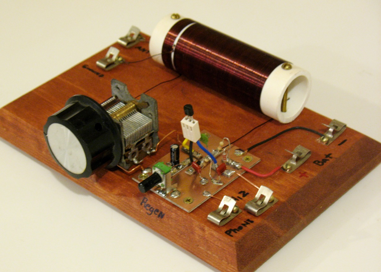
ElectroMaster. This circuit is a simple two transistor (2N2222) FM transmitter. No license is required for this transmitter according to FCC regulations regarding wireless microphones. If powered by a 9 volt battery and used with an antenna no longer than 12 inches, the transmitter will be within the FCC limits. The microphone is amplified by Q1.
* Eletrônica Circuito esquema transmissor FM espião com transistor
The circuit diagram shown for FM transmitter circuit and the electronic components are the resistor, capacitor, trimmer or variable capacitor, inductor (coil), transmitter, mic, 9v of power supply or 7809 Voltage regulator (in case if you are using input voltage more than 9v) and an antenna.
Simple Two Transistors AM Transmitter Circuit
T1 = 2N2222 M = Electret MIC. 1 Clip for 9 volt battery. Technical specifications : POWER SUPPLY: 9V Battery PP3 Power consumption: 5mA FREQUENCY: 70-110 MHz Distance Range: Over 100 meters Design#2 200 Meters Transmitter Circuit
High Power Am Transmitter Circuit Diagram
Data collection and use of cookies. This web site and our partners collect data and use cookies to improve the user experience, show personalized advertisement and gather statistics.

2n2222 fm transmitter circuit YouTube
2n2222 fm transmitter circuit inventor KR 296K subscribers Join Subscribe 383 17K views 2 years ago #inventor_KR You can buy all electronic components for the product here 👇👇👇👇👇👇.
Simple FM Transmitter with one Transistor
FM Transmitter Circuit Working Explanation To make the Simple FM Transmitter, we are using the condenser microphone that provides the audio signal. When the audio signal is from the microphone, it converts the signal into an electrical signal and then that signal penetrates the base of the transistor which increases the amplitude of the signal.

2N2222 General purpose NPN switching transistor Protostack
This circuit is a simple two transistor (2N2222) FM transmitter. No license is required for this transmitter according to FCC regulations regarding wireless microphones. If powered by a 9 volt battery and used with an antenna no longer than 12 inches, the transmitter will be within the FCC limits. The microphone is amplified by Q1.

2N2222 NPN BJT fade off controlled by capacitor RC time constant
This multipurpose FM transmitter circuit can be built on a compact size PCB, and there is no signal interference due to well-placed filter capacitors. To construct this circuit, start with Electret condenser microphone and apply bias through R1 Resistor, then connect output signal from mic to Q1 transistor base terminal through C1 and R2.
Simple FM Transmitter Circuit (88108MHz) With 2N2222 Transistor under
The Basics of Transmitters Fig. 2 — 100 100 OUTPUT RFC 2.5 mH 0.01 same thing, but have different circuit hookups. You may wish to gather the parts for the circuit of Fig. 3 and assemble it. This will give you valuable first-hand experience concerning oscillator operation.

Equivalent Transistor For 2n2222
The following typical RF transmitter block diagram shown below shows where the crystal oscillator/carrier oscillator is used. The following is the circuit schematic for the 2n2222 transistor based crystal oscillator. In the above circuit diagram, a crystal which ranges from 1MHz to 15MHz is used. This crystal along with the Q1 transistor forms.
Three Stage FM Transmitter using 2n3904 Transistor
Circuit Diagram: This fm transmitter electronic project is designed using common electronic parts and 2N2222 transistors. To get a bit of tuning out of the coil you could put a 4-40pF trimmer capacitor parallel over the 1 µH inductor.
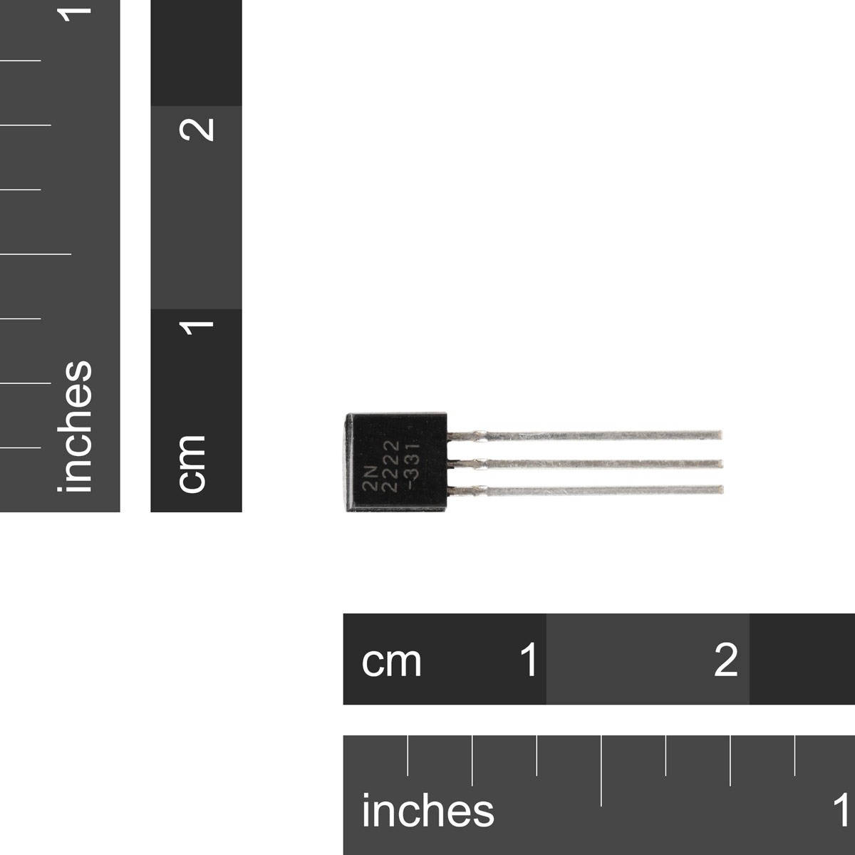
2N2222 General purpose NPN switching transistor Protostack
April 4, 2020 In this project, let's learn how to make a simple "Long-range FM transmitter" at a low cost using minimal components. As you can see in the diagram, the circuit is simple, easy to build and test. Let's begin to build our long-range FM transmitter. How To Build a Long Range FM Transmitter
Bird Microphone Transmitter 2N2222 PNP Transistor
This circuit is based on two NPN transistors of 2N2222 which is a low-power amplifier. At the first transistor stage, the input signal is preamplified and then the transistor T2 will Amplify the signal as a power amplifier and then amplified the signal to be modulated and transmitted through output as an antenna.
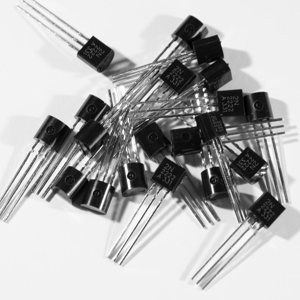
2N2222 NPN Transistor 5 or 10 Pack
Watch on The 2N2222 is an NPN bipolar junction transistor (BJT). BJTs can be used to amplify analog signals, but they can be used as switches as well. Here we'll show how to use as a switch. The example to show this will be based on lighting a bright LED that will need a voltage and current larger than what an Arduino UNO IO pin can supply.